Gen 3 Hub Units and ABS Magnetic Encoders: Structure, Signal and Sourcing Essentials
From discrete bearings to mechatronic assemblies — the three mistakes aftermarket sourcing makes most
Hub units have evolved from purely mechanical parts into electromechanical assemblies with integrated ABS magnetic encoders. This article walks through structural differences across three generations, how encoder signals work, the parameters that matter, and a practical checklist for sourcing and replacement.
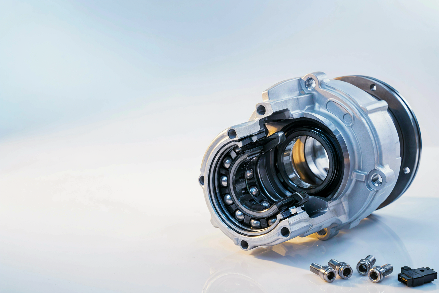
In the EU and US markets, ABS and ESC are mandatory equipment; in China and most export destinations, regulation is following fast. The net effect is that the hub bearing has moved from a purely mechanical part to a mechanical-plus-sensor hybrid assembly — the wheel speed signal is no longer delivered by a separate tone ring and sensor, but integrated inside the hub unit. Understanding this evolution is the precondition for getting aftermarket sourcing right.
From Gen 1 to Gen 3: what each structure solved
A Gen 1 hub unit is essentially a pre-assembled double-row angular contact ball bearing (or double-row tapered roller bearing); clearance and preload still need adjusting at installation. Gen 2 integrates the flange on the inner-ring side, eliminating some assembly steps. Gen 3 locks the two inner rings together via a swaged collar at the inner ring end — clearance is preset at the factory, and the unit installs without adjustment, greased and sealed for life. Current mainstream passenger cars use Gen 3 as both OE fitment and aftermarket replacement, with some newer platforms adopting Gen 4 products with further flange and sensor integration.
How the ABS signal is integrated
The key component is the magnetic encoder: a magnetized multi-pole ring integrated at the seal position or flange face of the hub unit, working with a Hall-element (active) or magnetoresistive (passive) sensor to output the wheel speed signal. Three parameters must be verified at sourcing:
- Active or passive: active encoders need ECU power supply and deliver better signal quality and low-speed performance; passive ones are self-generating and mechanically simpler. The two are not interchangeable;
- Encoder pole count: commonly 48, 64 or 96 poles, which must match the vehicle ECU's algorithm — a wrong pole count triggers fault codes or false ABS events immediately;
- Installation air gap: the gap between encoder and sensor is typically under 1 mm; press-fit distortion or knocks directly degrade signal quality.
The aftermarket sourcing checklist
Beyond the usual OE reference and crossover verification, for hub units with integrated ABS, confirm each item below:
- Confirm the vehicle's sensor type (active or passive) and encoder pole count — check the VIN rather than judging by appearance;
- Verify flange bolt-hole count, pitch circle diameter (PCD) and center bore;
- Verify spindle thread specification and lock-nut form (with or without locking tab, single-use or not);
- Confirm the accessory kit is complete: magnetic lock nut, circlip, dust cap — these small parts often decide installation success.
Three common mistakes during replacement
- Substituting a discrete bearing plus an outsourced tone ring for an integrated unit — clearance cannot be guaranteed, and encoder accuracy is out of the question;
- Pressing on the inner ring during installation — shock loads damage the raceways and the encoder ring; the correct practice is to press on the flange face only;
- Zipping the lock nut tight with an impact gun — Gen 3 preload is set at manufacture and the nut must be torqued to the vehicle's specification with a torque wrench; over-tightening equals premature failure.
Encoder-integrated versions of NTK's hub unit line are batch-sampled for signal and air gap, and we provide OE crossover reference tables organized by destination market. For technical documents or sample validation, contact [email protected].